How can we help?
Having trouble? Click here to access our troubleshooting guide.
Your Question:
Micron 60FF Engineer Support (Pijnenburg)
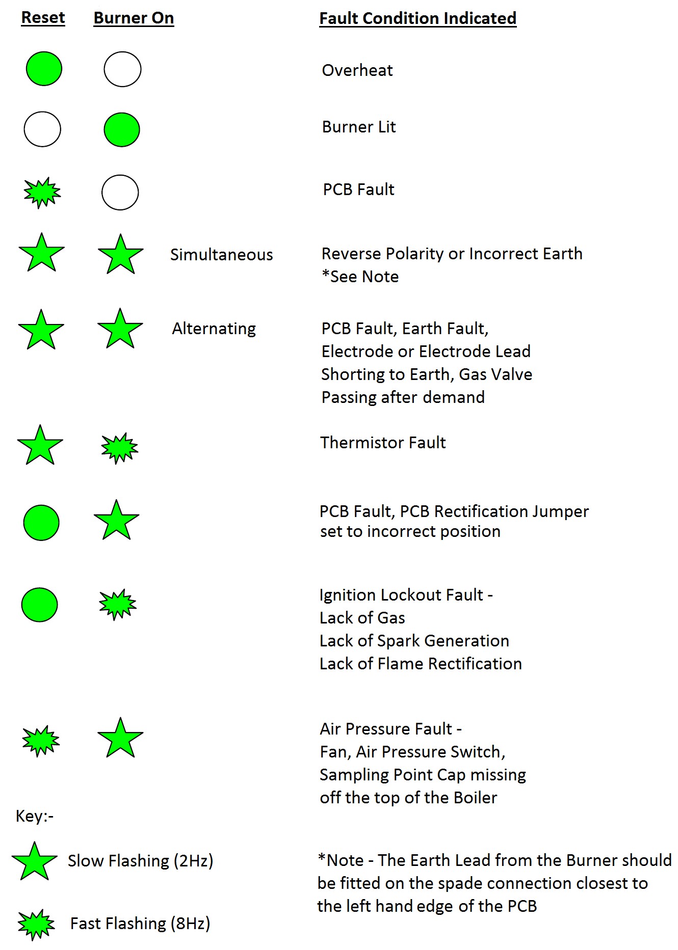
Micron 60FF Fault Finding
(Pijnenburg PCB Versions)
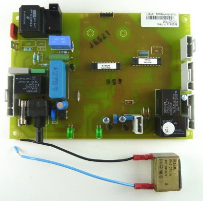
Pijnenburg PCB shown above with separate 250 microfarad capacitor
Micron 60FF Pijnenburg PCB Fault Finding Chart
Schematic Wiring Diagram (Pijnenburg PCB)

Component Tests - Micron 60FF with Pijnenburg PCB)
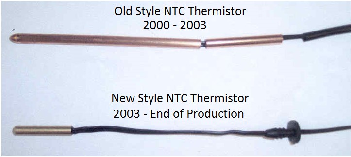
NTC Thermistor
Test with the power to the boiler turned OFF and the Thermistor disconnected from the PCB if necessary.
It should read 10Kohms -12Kohms at 20 – 25 degrees Celsius. The Resistance Range is 14Kohms (cold) to 2.5Kohms (hot). There were 2 styles of NTC Thermistor used on the Micron 60FF and both are interchangeable (See Below)
Fan
230vac across the Purple (L) and the Blue (N) wires at the Fan with demand. The Fan motor can also be tested for resistance, and with the power off it should measure approximately 50ohms.
Air Pressure Switch (At Rest)
It should read 230vac on the Red Wire (Common Contact) to a Neutral, 230vac on the Grey Wire (Normally Open Contact) to a Neutral, and 230vac on the Yellow Wire (Normally Closed Contact) to a Neutral.
Air Pressure Switch (Switch Made)
With the Fan running it should read 230vac on the Red Wire (Common Contact) to a Neutral, 230vac on the Grey Wire (Normally Open Contact) to a Neutral, and approximately 30vac on the Yellow Wire (Normally Closed Contact) to a Neutral.
The Air Pressure Switch can also be checked for operation with the power off in the following manner: In the rest position it should read continuity across the Common (Red Wire) and Normally Closed (Yellow Wire) contacts. When the Air Pressure Switch is “made” it should read continuity across the Common (Red Wire) and the Normally Open (Grey Wire) contacts. The minimum switching pressure for the Air Pressure Switch is approximately 0.8mbar.
Overheat Thermostat
It should read continuity across the 2 connections on the Overheat Thermostat itself (Brown wires)
The Overheat Thermostat will trip to an open circuit at approximately 94 degrees Celsius. The Overheat Thermostat will automatically reset itself once it has cooled down, but the appliance will still require resetting via the Control Knob on the front after an overheat fault to clear the fault light.
Gas Valve
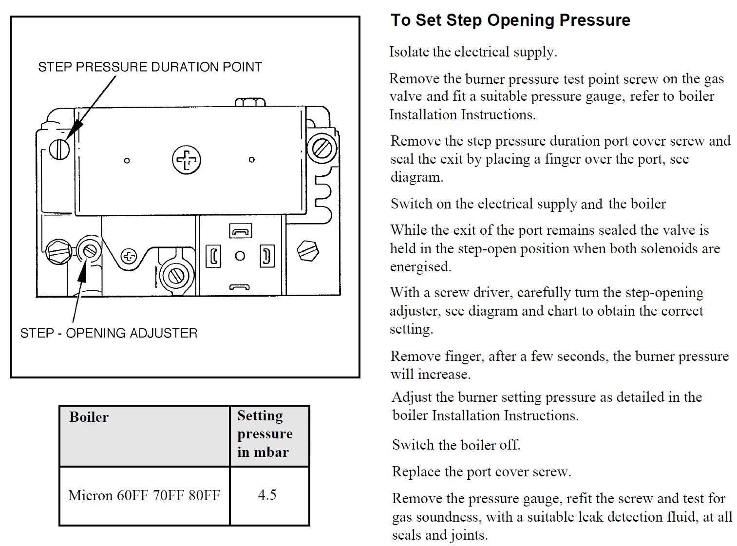
During spark ignition there should be 230vac across the Brown and Blue wires off the PCB to the Gas Valve Solenoid EV1, and 230vac across the Black and Blue wires off the PCB to the Gas Valve Solenoid EV2. Both solenoids are powered at the same time and there is an adjustable 4.5mbar step opening (ignition) pressure on the Micron 60FF (See information below on how to set this ignition pressure)
The resistance of the individual Gas Valve Solenoids can be measured as follows. With the power to the boiler turned OFF, remove the square black electrical connection plug off the Gas Valve and measure the resistance across the corresponding pins on the Gas Valve as marked below:
EV1 to COM = 800 – 900 ohms EV2 to COM = 800 – 900 ohms
Points to note on a Micron 60FF with Pijnenburg PCB
1 – The Pijnenburg PCB has a pre demand fan purge of approximately 10-15 seconds. When a demand is placed on the appliance from the Switched Live, the Fan will run for 10-15 seconds then stop. It will then start up again and go through the normal ignition sequence.
2 - The Micron 60FF has a Pump over-run function, so therefore it requires a permanent mains live supply as well as a switched live, and the system pump must be wired directly to the boiler.
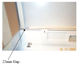
3 - On versions manufactured after June 2003 there is a 25mm gap in the bottom case seal at the right hand corner (looking from the front) to reduce potential flue noise on certain configurations. This is an approved Glow Worm modification, and tests have shown that the appliance casing seal still satisfies all of the relevant room sealed appliance standards. See photo below:
4 - All versions of the Micron 60FF PCB (Pektron, Pijnenburg & Ritter) are all interchangeable - E.G a Pijnenburg could replace a Pektron or a Ritter can be fitted in place of a Pijnenburg etc. The Pijnenburg PCB was used in production on the Micron 60FF between 2002 – 2005.
5 – A Micron 60FF fitted with a Pijnenburg PCB should have a separate “Capacitor” wired across the switched live (LS) and neutral (N) connections on the boilers electrical connection block. This 250 microfarad capacitor was added to remove abnormal influences from system controls (stray voltages and induced currents) that may cause the boiler to operate when the external programmer is not calling for heat (This can be common on Y Plan Systems fitted with Honeywell 3 Port Valve) On the Capacitor the Black Wire goes into the “LS” connection and the Blue Wire goes into the “N” connection on the boilers electrical connection block.
6 – When the Micron 60FF is fitted to a thermal store unit (e.g. Gledhill Boilermate) then a specially calibrated replacement NTC Thermistor should be fitted into the boiler in place of the original factory fitted NTC Thermistor. This specially calibrated NTC Thermistor will allow the boiler to satisfy the heat requirements of the Thermal Store. The Part Number for this specially calibrated NTC Thermistor is 2000802653.