How can we help?
Having trouble? Click here to access our troubleshooting guide.
Your Question:
Ultimate 30FF - 60FF Engineer Support
Welcome to the Engineer Technical Support section. Please use the different sections below to find answers to your technical questions. You can also find a range of useful contact numbers, including Technical support, here.
Fault Finding Information
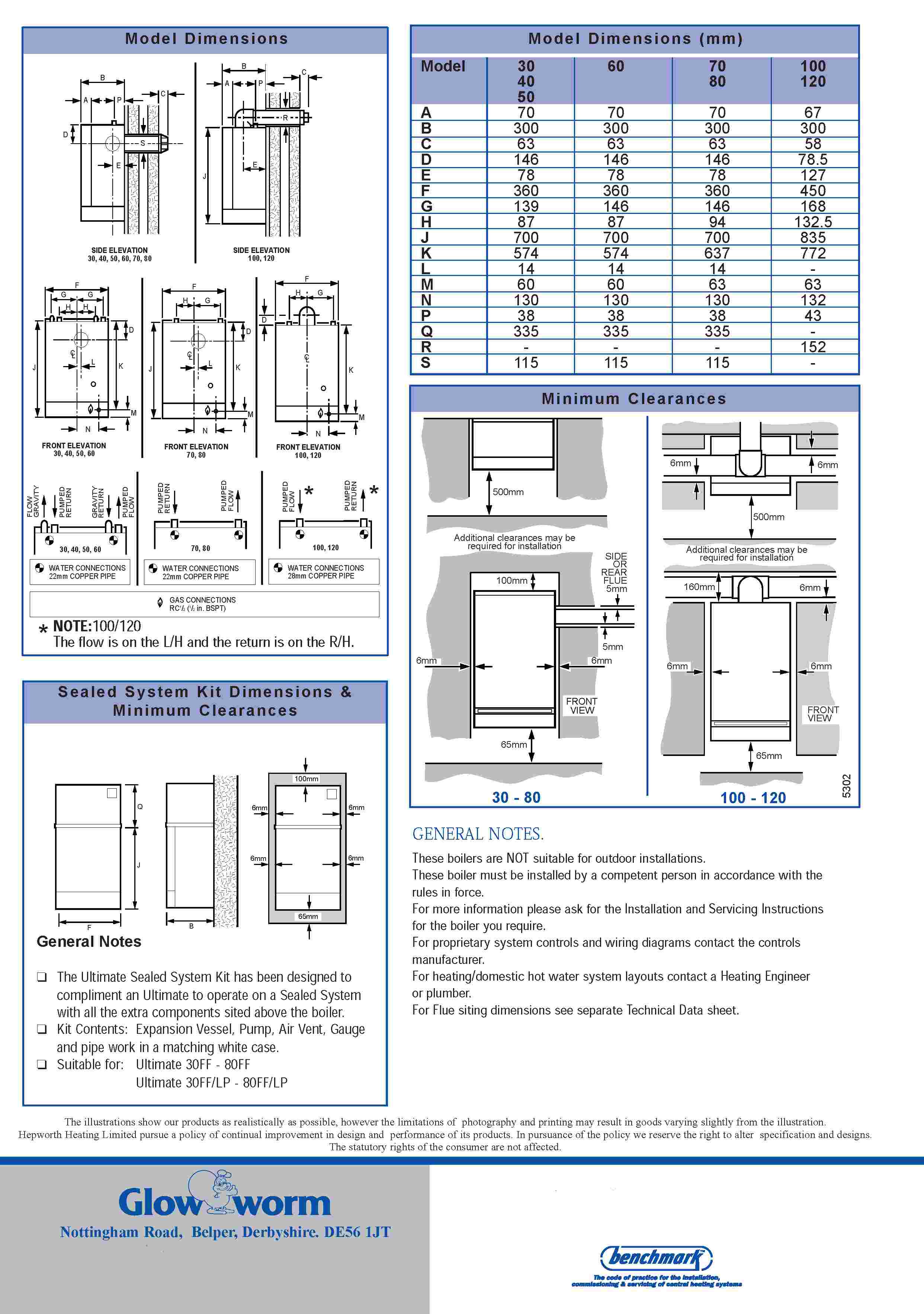
Technical Specification 30FF - 60FF
Fault Finding Lights (2 fuse PCB)
Later Versions with a 2 FUSE 7 WIRE PCB ONLY
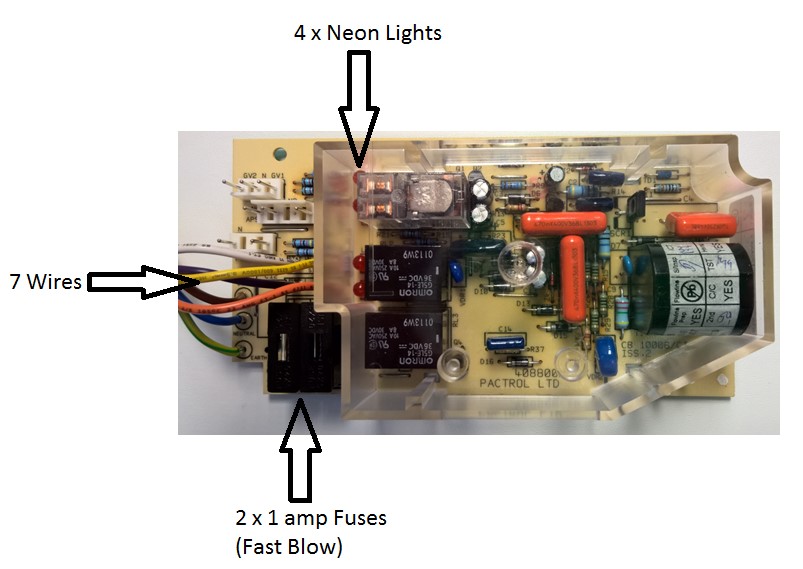
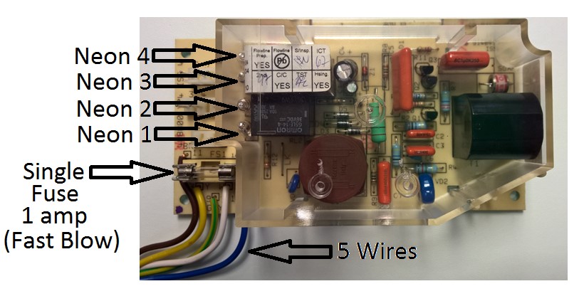
The later variants of the Ultimate 30FF use a PCB with 7 wires coming off it and 2 x 1 amp fuses as shown on the above photo. The Pump and a timed Pump Overrun function are controlled off the PCB on this version. The Pump Overrun function is timed to run for approximately 6-7 minutes after the demand has ceased (FULLY PUMPED SYSTEMS ONLY). The extra Fuse (F2) is there to protect the PCB from an electrical failure of the external system Pump. There are 4 neon sequence lights on the PCB to aid fault diagnosis.
Neon Indicators on 2 FUSE 7 WIRE PCB Versions
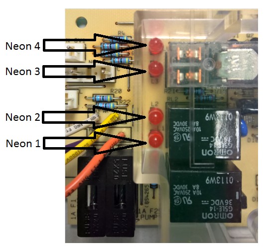
Neon Key
The 4 Neon indicators on the PCB are an aid to fault finding only. Failure of any of the Neon indicators does not warrant the replacement of an otherwise fully functioning Printed Circuit Board
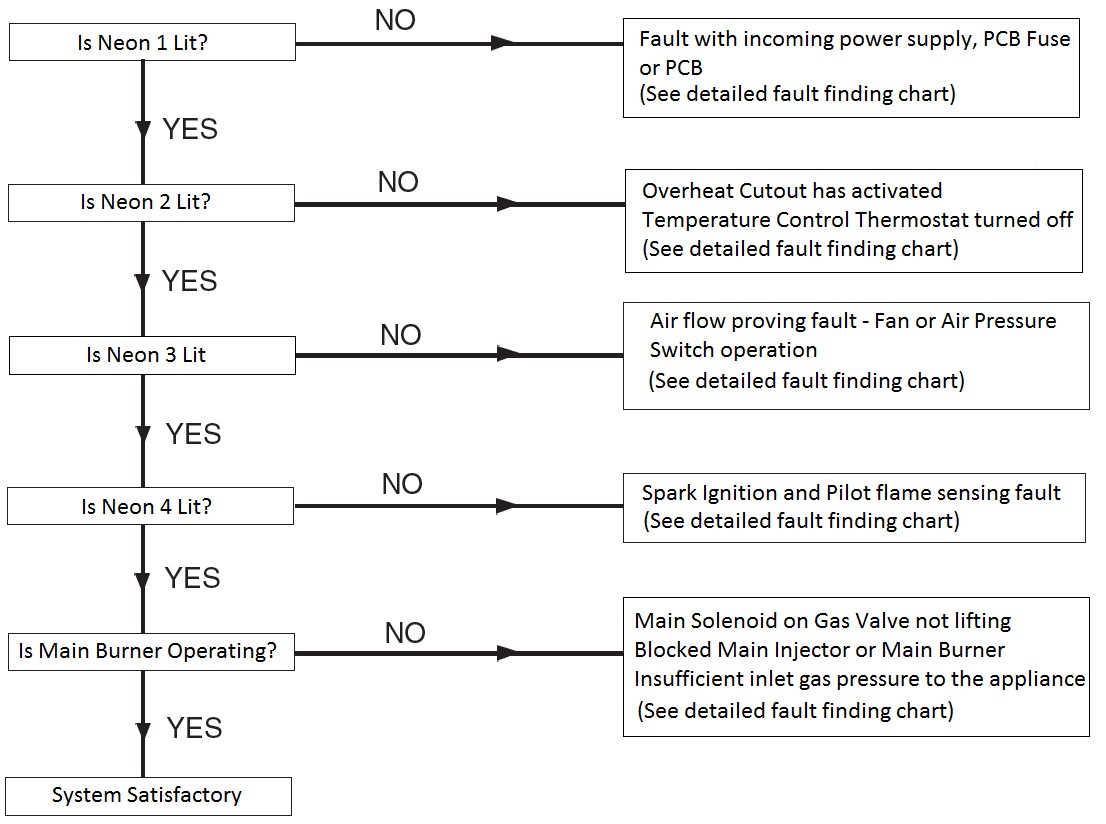
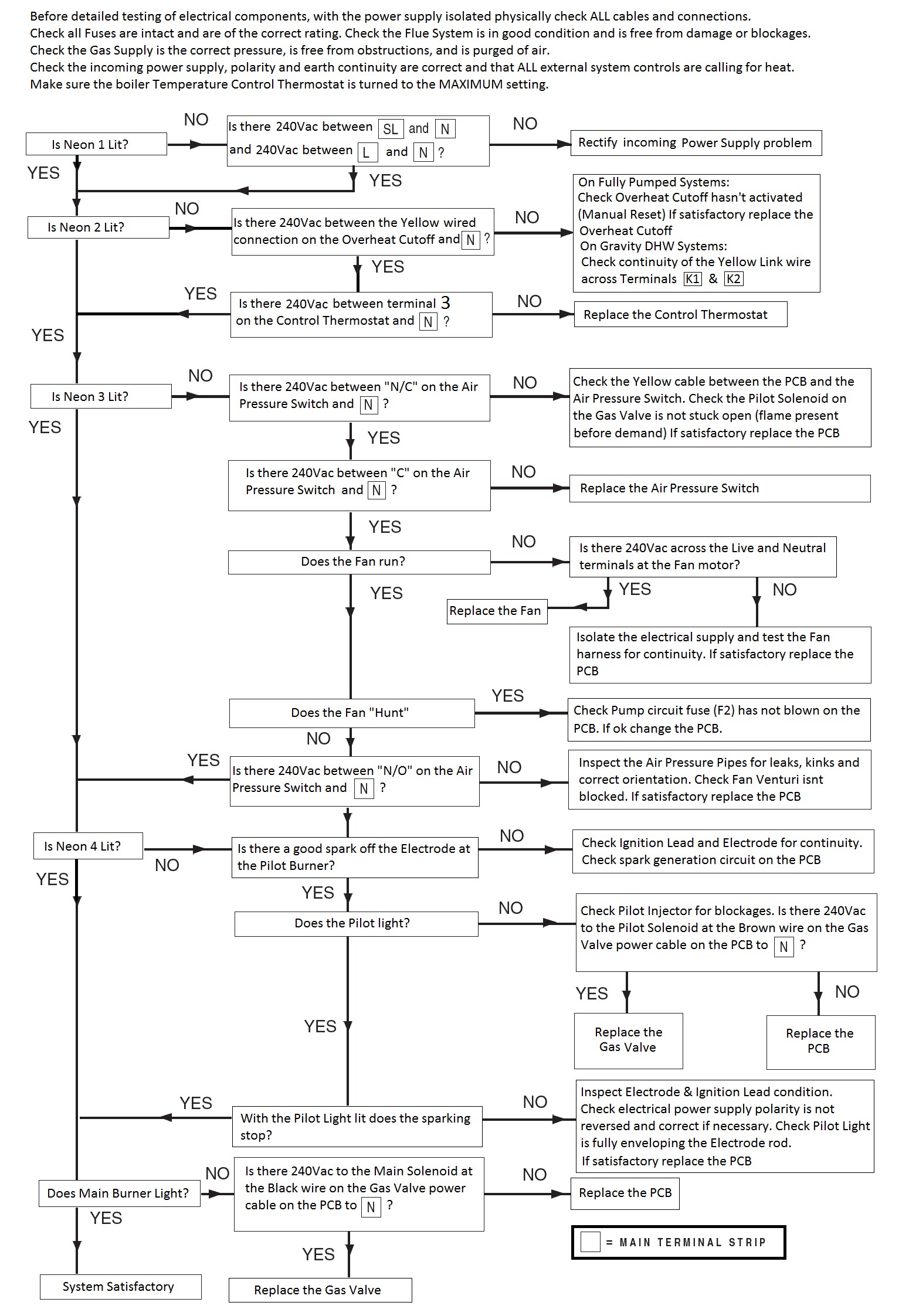
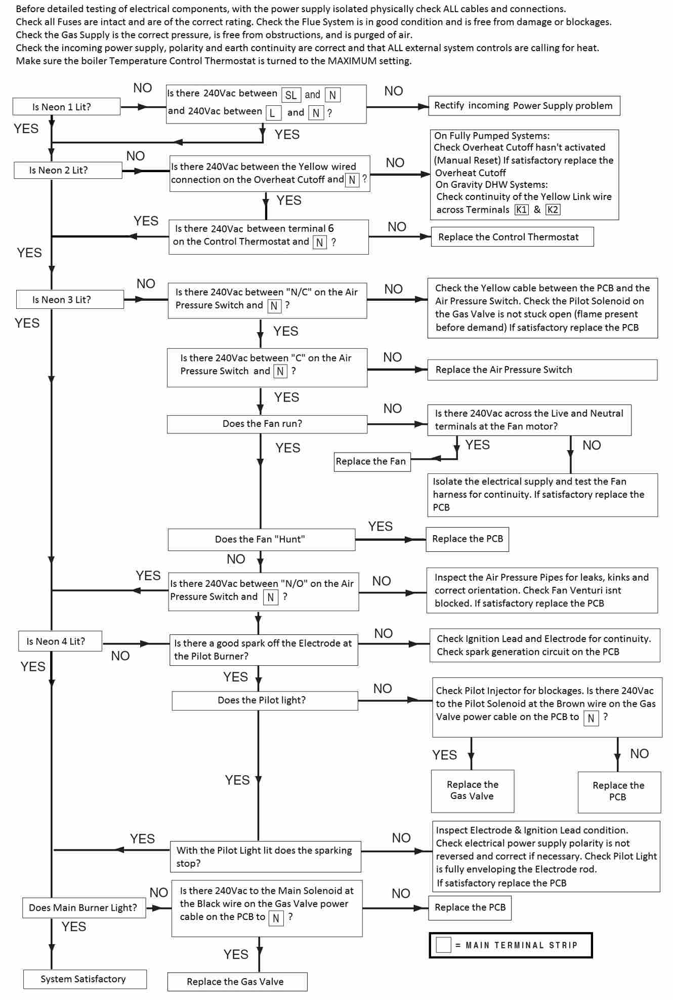
Ultimate 30FF - 60FF Fault Finding Chart
Component Voltages (2 fuse PCB)
PCB Fuses
F1 = 1 Amp (Fast Blow) – 240Vac to Neutral on each side of the Fuse
F2 = 1 Amp (Fast Blow) – 240Vac to Neutral on each side of the Fuse
Overheat Cutoff Thermostat
240Vac Input on the White wire to Neutral & 240Vac Output on Yellow wire to Neutral (If the Overheat Thermostat hasn’t tripped)
Temperature Control Thermostat
240Vac Input on to Pin 2 (Yellow wire) and 240Vac Output from Pin 3 (Yellow wire) with stat turned ON (set point higher than boiler temperature)
Air Pressure Switch
Works on 240Vac inputs and outputs.
Before the APS makes there will be 240Vac on the Yellow (N/C) wire to N, and 240Vac on the Red (C) wire to N. When the Fan runs and the APS makes there will be 240Vac on the Red (C) wire to N, and 240Vac on the Black (N/O) wire to N.
The APS can also be tested with the power off in the following manner if required:
In the rest position you should record Continuity across the COM & N/C contacts on the Air Pressure Switch
In the “made” position you should record continuity across the COM & N/O contacts on the Air Pressure Switch
APS Wire Colours:
Red = COM
Yellow = N/C
Black = N/O
APS Pipework Orientation:
At the APS:
Red Pipe = Bottom Connection
Clear Pipe = Top Connection
At the Fan:
Red Pipe = Rear Connection
Clear Pipe = Front Connection
Fan
240Vac across the Red (L) & Blue (N) wires on demand at either the Fan motor or the PCB Plug
Gas Valve
(This is tested on the gas valve power feed plug on the PCB)
Pilot Solenoid – 240Vac on the Brown wire to Neutral on demand
Main Burner Solenoid – 240Vac on the Black wire to Neutral once the pilot flame rectification has proved (Neon 4 lit on the PCB)
Feed To External System Pump
240Vac on Terminal “P” to Neutral on the Boiler’s electrical terminal strip. This voltage comes from the Purple wire off the PCB on demand from external heating controls and when the timed pump overrun function is active – FULLY PUMPED SYSTEMS ONLY
Sequence of Operation (2 fuse PCB)
Sequence Of Operation – Fully Pumped Systems
1 – 240Vac Permanent Live supply from fused spur & 240Vac Switched Live supply from external heating controls must be present across terminals L & N and SL & N respectively. The PCB will also put 240Vac up the Purple wire on to Terminal “P” of the electrical connection block to run the external system pump. (NEON 1 LIT ON PCB)
2 – 240Vac leaves the PCB on the White wire to Overheat Stat (via “K2” on the terminal strip) then out of the Overheat Stat on the Yellow wire which feeds the Temperature Control Thermostat input Pin 2 (via “K1” on the terminal strip). With the Temperature Control Thermostat calling for heat, 240Vac leaves the Temperature Control Thermostat on the Yellow wire Pin 3 back to the PCB. (NEON 2 LIT ON PCB)
3 – 240Vac then leaves the PCB on the Yellow wire to the Air Pressure Switch N/O contact, goes through the Air Pressure Switch and comes out on the Red wire COM contact back to the PCB (This function is carried out to prove the Air Pressure Switch is in the rest position prior to Fan Operation)
Once the PCB has seen 240Vac on the Red wire back from the Air Pressure Switch to prove it is in the rest position, the PCB puts 240Vac to the Fan. When the Fan runs it switches the Air Pressure Switch from the N/C position to the N/O position and puts 240Vac on the Black N/O wire which feeds back to the PCB. When the PCB sees this voltage it starts the Spark Generator. (NEON 3 LIT ON PCB)
4 – The PCB then puts 240Vac on the Brown wire to the Pilot Solenoid (EV1) on the Gas Valve. Once the Pilot Solenoid lifts and allows gas to flow through to the Pilot Burner via the Pilot Tube and the Pilot Injector, the Spark Electrode will light the Pilot Flame. Once the Pilot Flame has lit, it hits the tip of the Spark Electrode and Flame Rectification takes place. (NEON 4 LIT ON PCB)
* NOTE - It uses the same lead and electrode for spark ignition and flame rectification functions
5 – Once Flame Rectification has taken place, the Spark Generator will stop and the PCB will put 240Vac on the Black wire to the Main Burner Solenoid (EV2) on the Gas Valve. Once the Main Burner Solenoid lifts it allows gas to flow through to the Main Burner via the Main Burner Injector. This gas is then lit by the Pilot Flame and the Main Burner flame will be established.
6 – Once the demand has ceased the Boiler will shut down, but the PCB will continue to run the External System Pump on a timed pump overrun for approximately 7 minutes.
Sequence Of Operation – Gravity DHW/Pumped Heating Systems
1 – 240Vac switched live from external heating controls must be present across terminals SL & N, and the Red Link wire must be fitted between terminals 9 & SL (NEON 1 LIT ON PCB)
2 – 240Vac leaves the PCB on the White wire to “K2” on the terminal strip, then through the Overheat Thermostat Link wire and back out on the Yellow wire “K1” on the terminal strip to Pin 2 (Input) on the Temperature Control Thermostat. With the Temperature Control Thermostat “On” 240Vac leaves the Temperature Control Thermostat on Pin 3 Yellow wire (Output) back to the PCB (NEON 2 LIT ON PCB)
3 – 240Vac then leaves the PCB on the Yellow wire to the Air Pressure Switch N/O contact, goes through the Air Pressure Switch and comes out on the Red wire COM contact back to the PCB (This function is carried out to prove the Air Pressure Switch is in the rest position prior to Fan Operation)
Once the PCB has seen 240Vac on the Red wire back from the Air Pressure Switch to prove it is in the rest position, the PCB puts 240Vac to the Fan. When the Fan runs it switches the Air Pressure Switch from the N/C position to the N/O position and puts 240Vac on the Black N/O wire which feeds back to the PCB. When the PCB sees this voltage it starts the Spark Generator. (NEON 3 LIT ON PCB)
4 – The PCB then puts 240Vac on the Brown wire to the Pilot Solenoid (EV1) on the Gas Valve. Once the Pilot Solenoid lifts and allows gas to flow through to the Pilot Burner via the Pilot Tube and the Pilot Injector, the Spark Electrode will light the Pilot Flame. Once the Pilot Flame has lit, it hits the tip of the Spark Electrode and Flame Rectification takes place. (NEON 4 LIT ON PCB)
* NOTE - It uses the same lead and electrode for spark ignition and flame rectification functions
5 – Once Flame Rectification has taken place, the Spark Generator will stop and the PCB will put 240Vac on the Black wire to the Main Burner Solenoid (EV2) on the Gas Valve. Once the Main Burner Solenoid lifts it allows gas to flow through to the Main Burner via the Main Burner Injector. This gas is then lit by the Pilot Flame and the Main Burner flame will be established.
6 – Once the demand has ceased the Boiler will shut down. (There is no boiler controlled Pump Overrun function when the boiler is connected to a Gravity DHW/Pumped Heating system).
Schematic wiring diagram (2 fuse PCB)
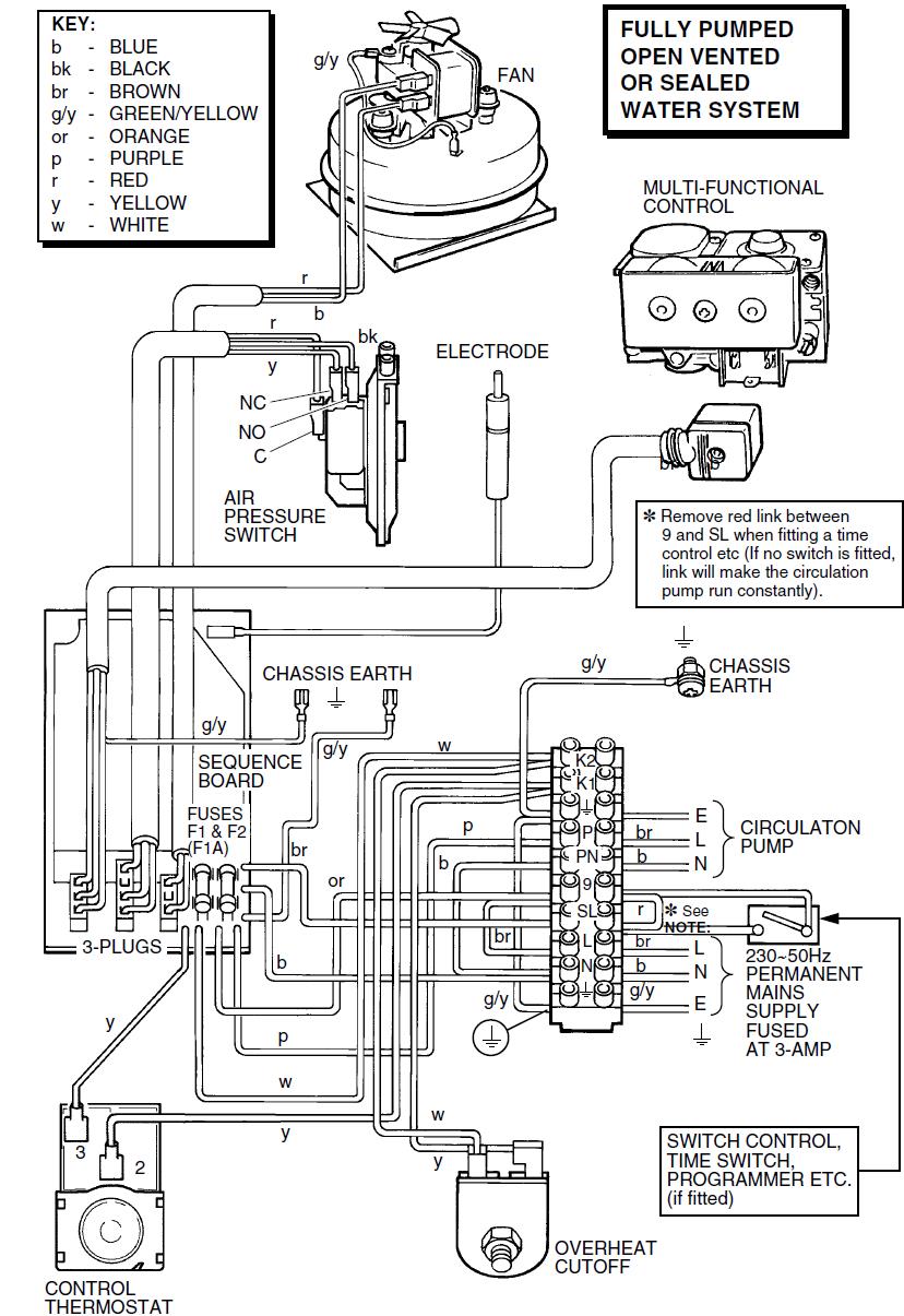
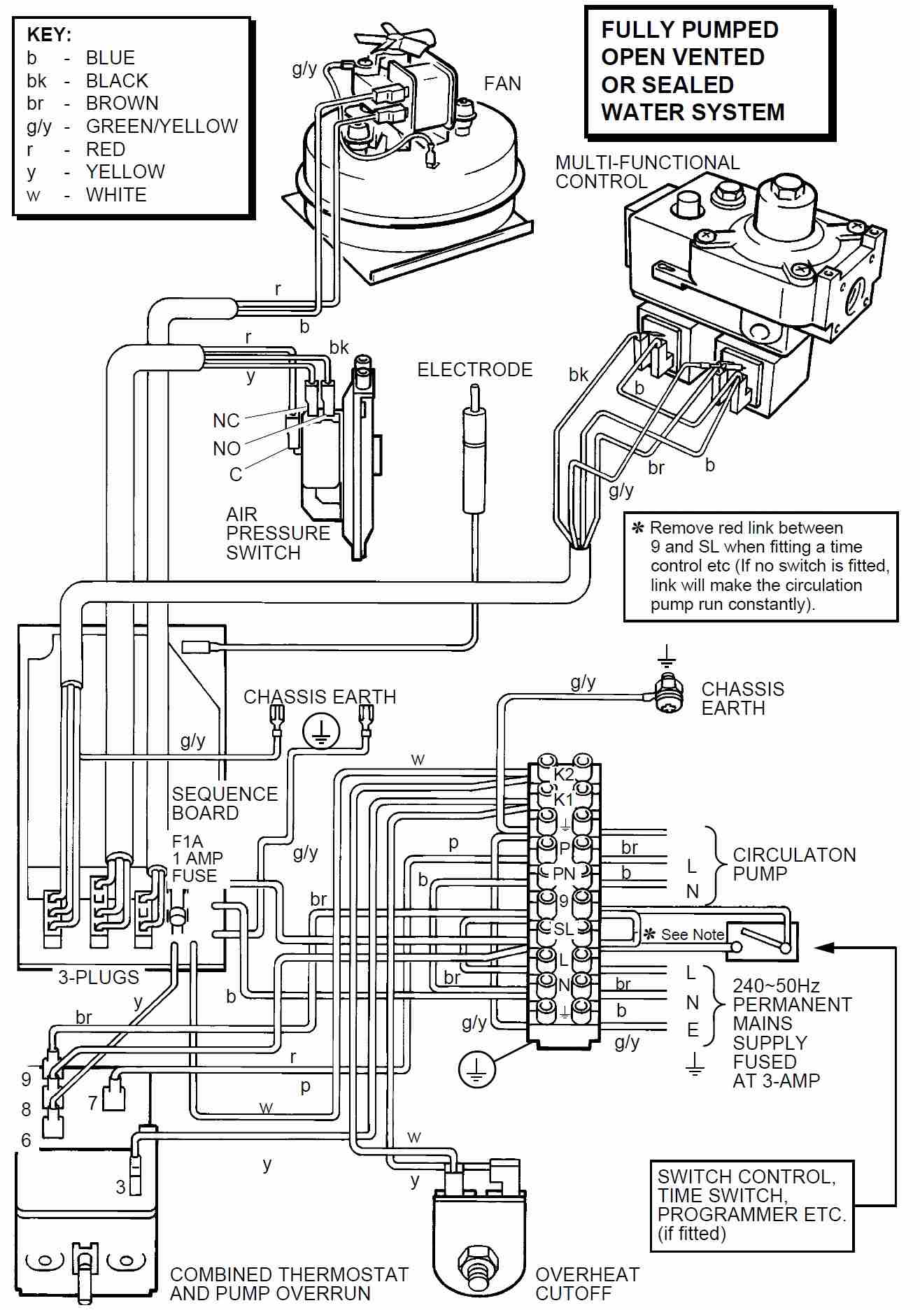
Schematic Wiring Diagram For Fully Pumped Systems
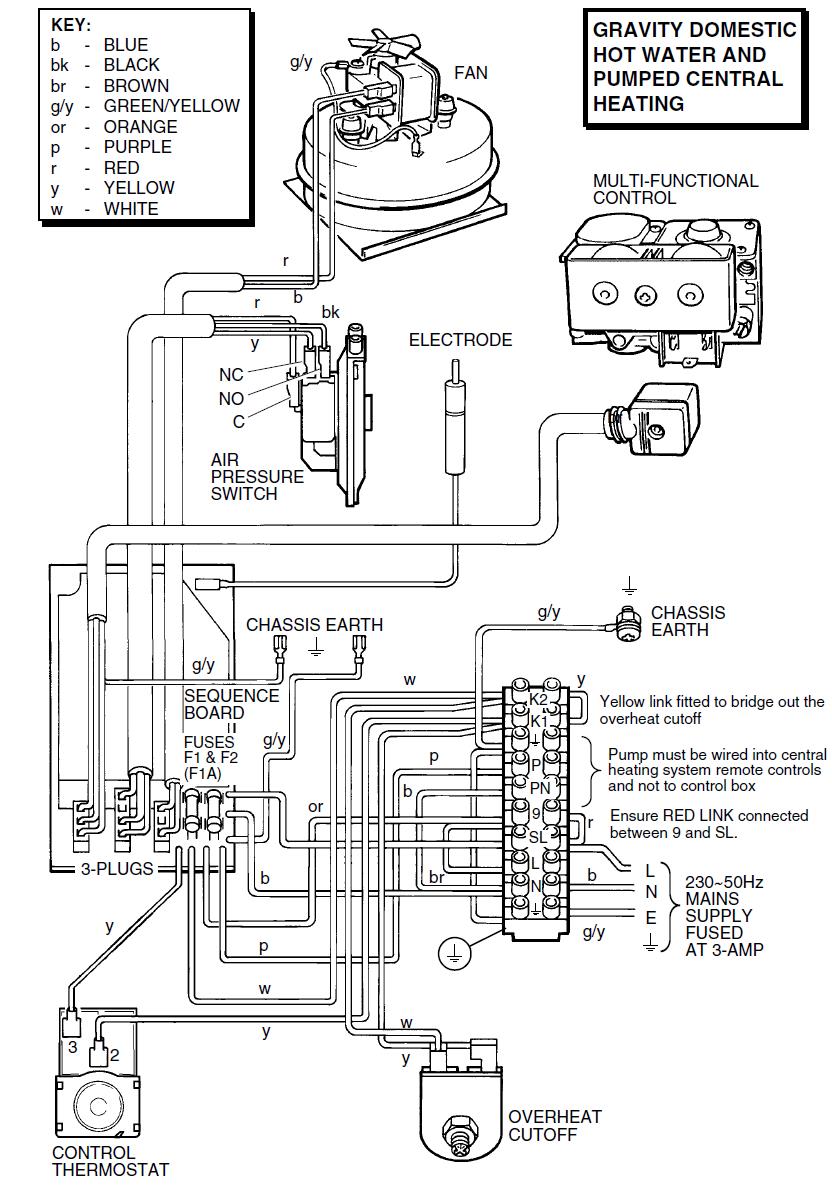
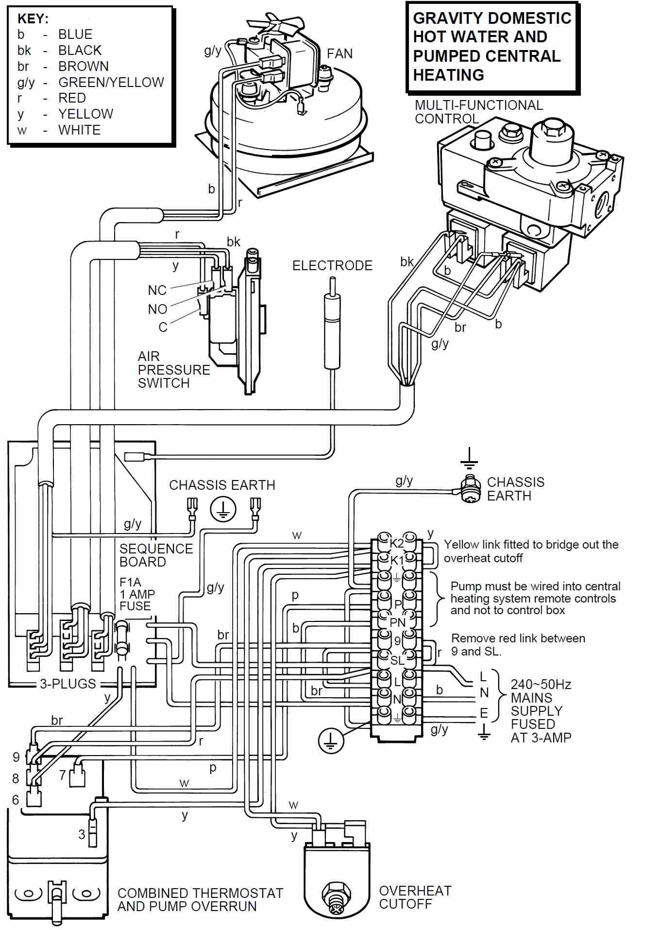
Schematic Diagram For Gravity DHW/Pumped Heating Systems
Fault Finding Lights (1 fuse PCB)
Ultimate 30FF-60FF Fault Finding
Early Versions ONLY (with 1 FUSE/5 WIRE PCB fitted)
The earlier variants of the Ultimate 30FF-60FF range use a PCB with 5 wires coming off it and a single 1 amp fuse as shown on the above photo. The Pump and the Pump Overrun functions are controlled off the Boiler Thermostat on versions fitted with this PCB. The Pump Overrun is temperature controlled, and will run the Pump after the demand has ceased until the boiler temperature drops to below 65 degrees celsius. There are 4 neon sequence lights on the PCB to aid fault diagnosis.
Neon Key
The 4 Neon indicators on the PCB are an aid to fault finding only. Failure of any of the Neon indicators does not warrant the replacement of an otherwise fully functioning Printed Circuit Board

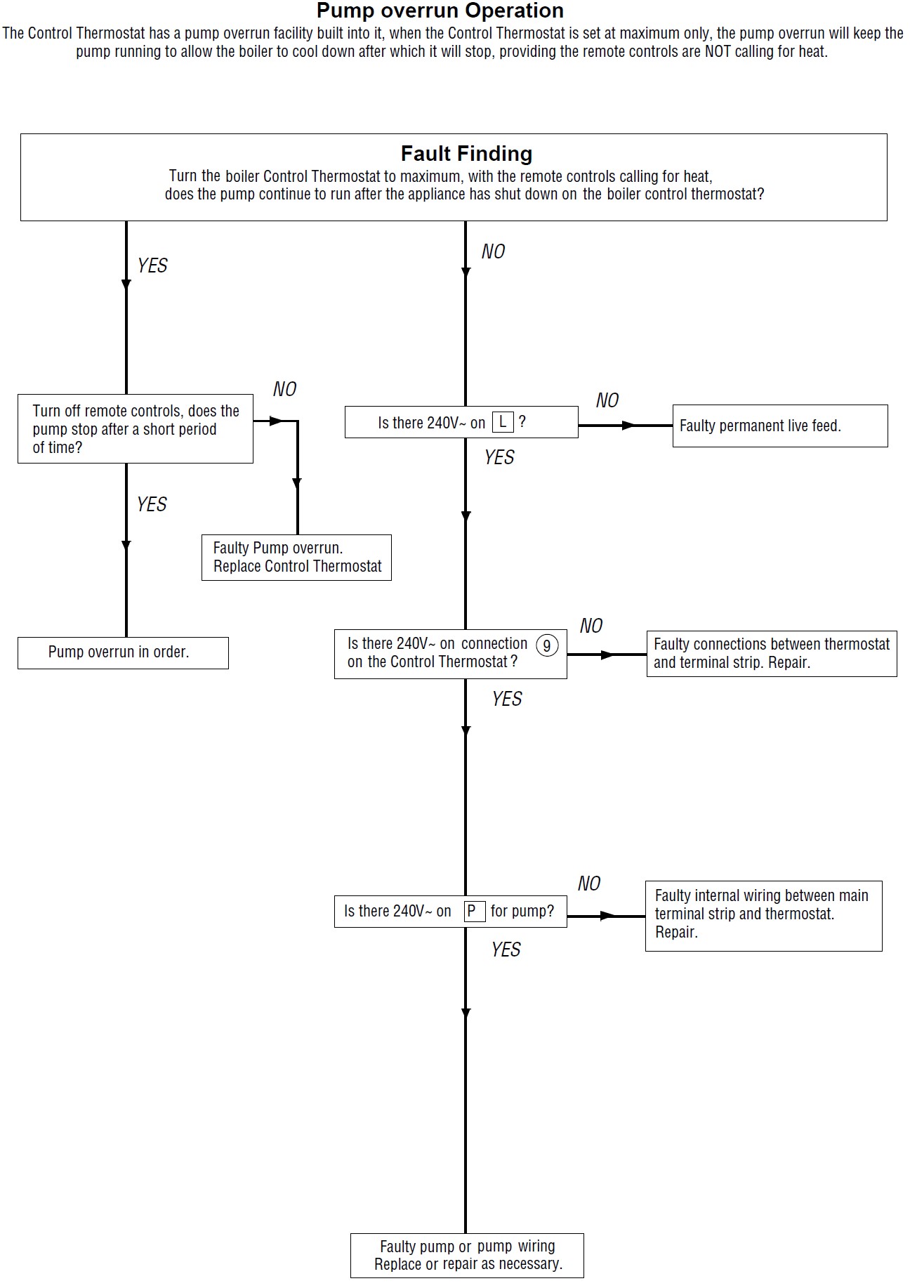
Pump Overrun Fault Finding Chart
FULLY PUMPED SYSTEMS ONLY
Component Voltages (1 fuse PCB)
Ultimate 30FF-60FF Fault Finding Chart – 1 Fuse/5 Wire Versions
Component Voltages
PCB Fuse
1 Amp (Fast Blow) – 240Vac to Neutral on each side of the Fuse
Overheat Cutoff Thermostat
240Vac Input on the White wire to Neutral & 240Vac Output on Yellow wire to Neutral (If the Overheat Thermostat hasn’t tripped)
Temperature Control Thermostat
240Vac permanent live supply to stat on Pin 9 (Brown Wire)
240Vac switched live supply to stat from external system controls to pin 8 (Red wire)
Pump Live supply from stat to Pump on Pin 7 (Purple wire) – Fully Pumped Systems Only
Temperature On/Off contacts are 240Vac Input on to Pin 3 (Yellow wire) and 240Vac Output from Pin 6 (Yellow Wire) with stat ON (set point higher than boiler temperature)
Air Pressure Switch
Works on 240Vac inputs and outputs.
Before the APS makes there will be 240Vac on the Yellow (N/C) wire to N, and 240Vac on the Red (C) wire to N. When the Fan runs and the APS makes there will be 240Vac on the Red (C) wire to N, and 240Vac on the Black (N/O) wire to N.
The APS can also be tested with the power off in the following manner if required:
In the rest position you should record Continuity across the COM & N/C contacts on the Air Pressure Switch
In the “made” position you should record continuity across the COM & N/O contacts on the Air Pressure Switch
APS Wire Colours:
Red = COM
Yellow = N/C
Black = N/O
APS Pipework Orientation:
At the APS:
Red Pipe = Bottom Connection
Clear Pipe = Top Connection
At the Fan:
Red Pipe = Rear Connection
Clear Pipe = Front Connection
Fan
240Vac across the Red (L) & Blue (N) wires on demand at either the Fan motor or the PCB Plug
Gas Valve
(This is tested on the gas valve power feed plug on the PCB)
Pilot Solenoid – 240Vac on the Brown wire to Neutral on demand
Main Burner Solenoid – 240Vac on the Black wire to Neutral once the pilot flame rectification has proved (Neon 4 lit on the PCB)
Voltage to the System Pump – FULLY PUMPED SYSTEMS ONLY
240Vac on terminal “P” to “N” on the boilers electrical terminal strip (This supply comes from the Temperature Control Thermostat Pin 7 purple wire)
Sequence of Operation (1 fuse PCB)
Sequence Of Operation – FULLY PUMPED SYSTEMS
1 – 240Vac Permanent Live supply from the fused spur to Pin 9 on the Temperature Control Thermostat (via the link wire fitted between terminals “L” and “9“on the boilers electrical terminal strip) & 240Vac Switched Live supply from external heating controls to Pin 8 on the Temperature Control Thermostat (Red Wire) and the PCB (Brown Wire) simultaneously. The Temperature Control Thermostat will then put 240Vac up the Purple wire off Pin 7 to Terminal “P” on the electrical connection block to run the external system pump. (NEON 1 LIT ON PCB)
2 – 240Vac leaves the PCB on the White wire to Overheat Stat (via “K2” on the terminal strip) then out of the Overheat Stat on the Yellow wire which feeds the Temperature Control Thermostat input Pin 3 (via “K1” on the terminal strip). With the Temperature Control Thermostat calling for heat, 240Vac leaves the Temperature Control Thermostat on the Yellow wire Pin 6 back to the PCB.
(NEON 2 LIT ON PCB)
3 – 240Vac then leaves the PCB on the Yellow wire to the Air Pressure Switch N/O contact, goes through the Air Pressure Switch and comes out on the Red wire COM contact back to the PCB (This function is carried out to prove the Air Pressure Switch is in the rest position prior to Fan Operation)
Once the PCB has seen 240Vac on the Red wire back from the Air Pressure Switch to prove it is in the rest position, the PCB puts 240Vac to the Fan. When the Fan runs it switches the Air Pressure Switch from the N/C position to the N/O position and puts 240Vac on the Black N/O wire which feeds back to the PCB. When the PCB sees this voltage it starts the Spark Generator. (NEON 3 LIT ON PCB)
4 – The PCB then puts 240Vac on the Brown wire to the Pilot Solenoid (EV1) on the Gas Valve. Once the Pilot Solenoid lifts and allows gas to flow through to the Pilot Burner via the Pilot Tube and the Pilot Injector, the Spark Electrode will light the Pilot Flame. Once the Pilot Flame has lit, it hits the tip of the Spark Electrode and Flame Rectification takes place. (NEON 4 LIT ON PCB)
* NOTE - It uses the same lead and electrode for spark ignition and flame rectification functions
5 – Once Flame Rectification has taken place, the Spark Generator will stop and the PCB will put 240Vac on the Black wire to the Main Burner Solenoid on the Gas Valve. Once the Main Burner Solenoid lifts it allows gas to flow through to the Main Burner via the Main Burner Injector. This gas is then lit by the Pilot Flame and the Main Burner flame will be established.
6 – Once the demand has ceased the Boiler will shut down. If the Temperature Control Thermostat is set to the maximum temperature setting it will continue to run the External System Pump on a temperature controlled pump overrun until the internal boiler temperature drops to approximately 65 degrees Celsius or less.
Sequence Of Operation – GRAVITY DHW/PUMPED HEATING SYSTEMS
1 – A 240Vac Switched Live supply from external heating controls simultaneously supplies Pin 8 on the Temperature Control Thermostat (Red Wire) the PCB (Brown Wire) and Pin 9 on the Temperature Control Thermostat (Brown Wire) via the link wire fitted between terminals “SL” & “9” on the boilers electrical terminal strip (NEON 1 LIT ON PCB)
2 – 240Vac leaves the PCB on the White wire to “K2” on the terminal strip, then through the Overheat Thermostat Link wire and back out on the Yellow wire “K1” on the terminal strip to Pin 3 (Input) on the Temperature Control Thermostat. With the Temperature Control Thermostat “On” 240Vac leaves the Temperature Control Thermostat on Pin 6 Yellow wire (Output) back to the PCB (NEON 2 LIT ON PCB)
3 – 240Vac then leaves the PCB on the Yellow wire to the Air Pressure Switch N/O contact, goes through the Air Pressure Switch and comes out on the Red wire COM contact back to the PCB (This function is carried out to prove the Air Pressure Switch is in the rest position prior to Fan Operation)
Once the PCB has seen 240Vac on the Red wire back from the Air Pressure Switch to prove it is in the rest position, the PCB puts 240Vac to the Fan. When the Fan runs it switches the Air Pressure Switch from the N/C position to the N/O position and puts 240Vac on the Black N/O wire which feeds back to the PCB. When the PCB sees this voltage it starts the Spark Generator. (NEON 3 LIT ON PCB)
4 – The PCB then puts 240Vac on the Brown wire to the Pilot Solenoid on the Gas Valve. Once the Pilot Solenoid lifts and allows gas to flow through to the Pilot Burner via the Pilot Tube and the Pilot Injector, the Spark Electrode will light the Pilot Flame. Once the Pilot Flame has lit, it hits the tip of the Spark Electrode and Flame Rectification takes place. (NEON 4 LIT ON PCB)
* NOTE - It uses the same lead and electrode for spark ignition and flame rectification functions
5 – Once Flame Rectification has taken place, the Spark Generator will stop and the PCB will put 240Vac on the Black wire to the Main Burner Solenoid on the Gas Valve. Once the Main Burner Solenoid lifts it allows gas to flow through to the Main Burner via the Main Burner Injector. This gas is then lit by the Pilot Flame and the Main Burner flame will be established.
6 – Once the demand has ceased the Boiler will shut down. (There is no boiler controlled Pump Overrun function when the boiler is connected to a Gravity DHW/Pumped Heating system)
Schematic wiring diagram (1 fuse PCB)
Schematic Wiring Diagram - FULLY PUMPED SYSTEMS
Schematic Diagram - GRAVITY DHW/PUMPED HEATING SYSTEMS
Gas Settings
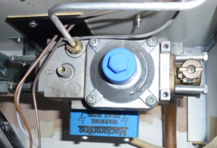
On the early versions of the Ultimate 30FF-60FF there could be up to 3 different Gas Valves fitted into the appliance. Please see important information below explaining the different gas valves and the compatibility issues that may arise:
The original Gas Valve that was fitted in to the appliance was the Johnson Maclarenline valve as shown below:
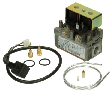
This Johnson Maclarenline valve is no longer available as a spare part. If a new Gas Valve is required for a boiler that has one of these valves fitted, you will need to use the S.I.T Gas Valve Conversion Kit (Part Number - 2000801129) as shown below:
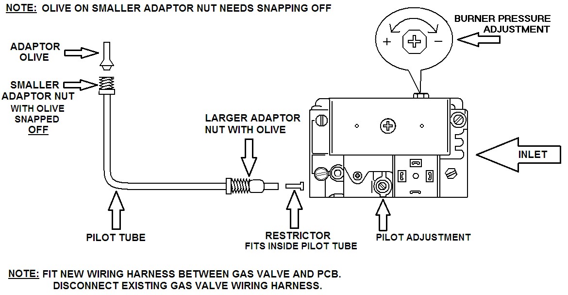
This S.I.T Gas Valve Conversion Kit is fitted into the boiler in the following manner:
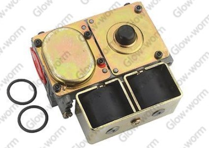
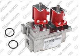
Later versions of Ultimate 30FF-60FF had the S.I.T valve already fitted into it from the factory. If a new Gas Valve is required for a boiler that has one of these valves fitted, the valve can be ordered as a separate part (Part Number - 2000801020) and the conversion kit would not be required, as shown below:
For a brief period the Ultimate 30FF-60FF range were fitted with a Honeywell VR4700 Gas Valve. No other Gas Valve is compatible with this version of the boiler, so if the Gas Valve fails you MUST use the Honeywell Gas Valve ONLY as a replacement part (Part Number – 800857) as shown below:
NOTE: For any appliance specific information regarding burner pressure figures and adjustment procedures, please consult the appliance specific Installation & Servicing manual for further details.
(Installation & Servicing manuals can be downloaded via the Glow worm website at www.glow-worm.co.uk if required)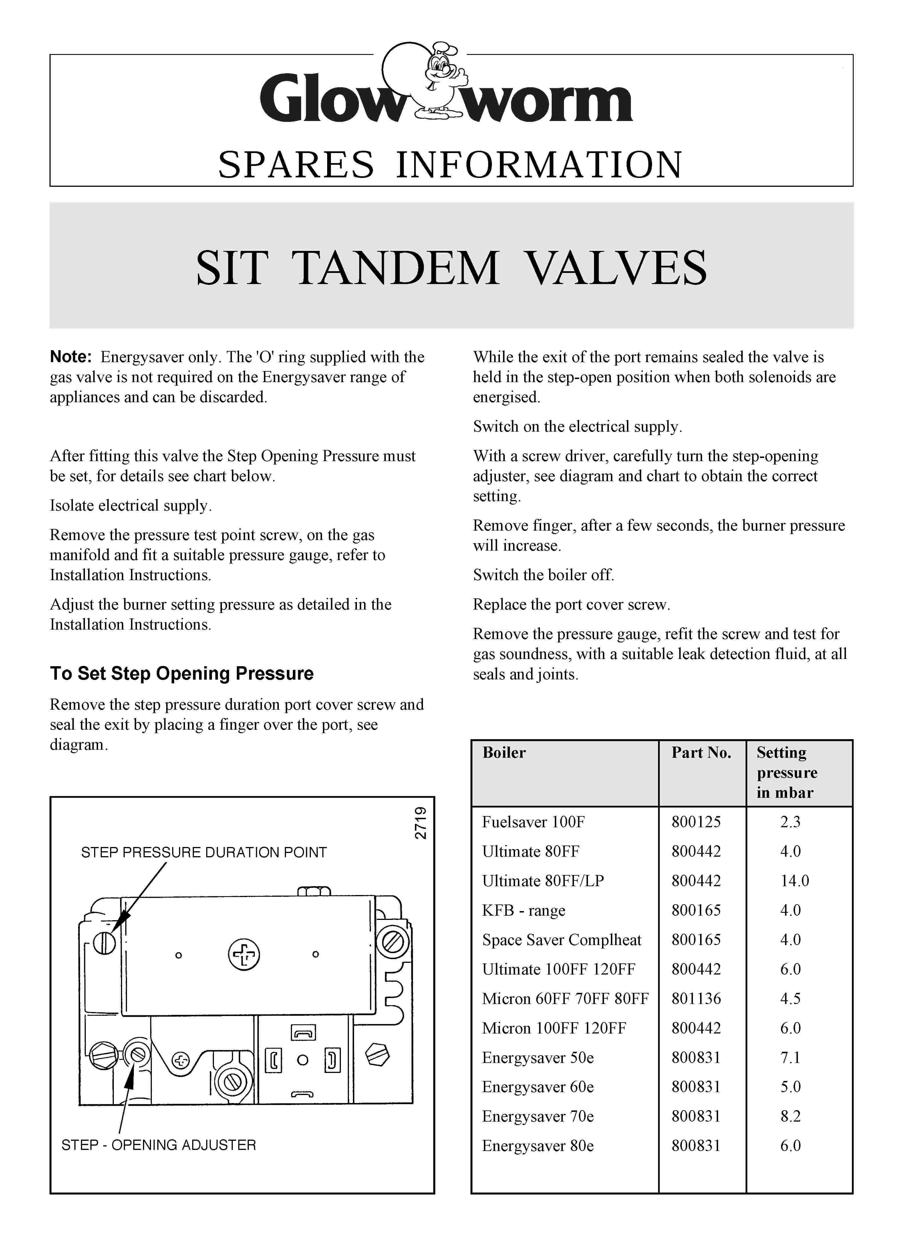
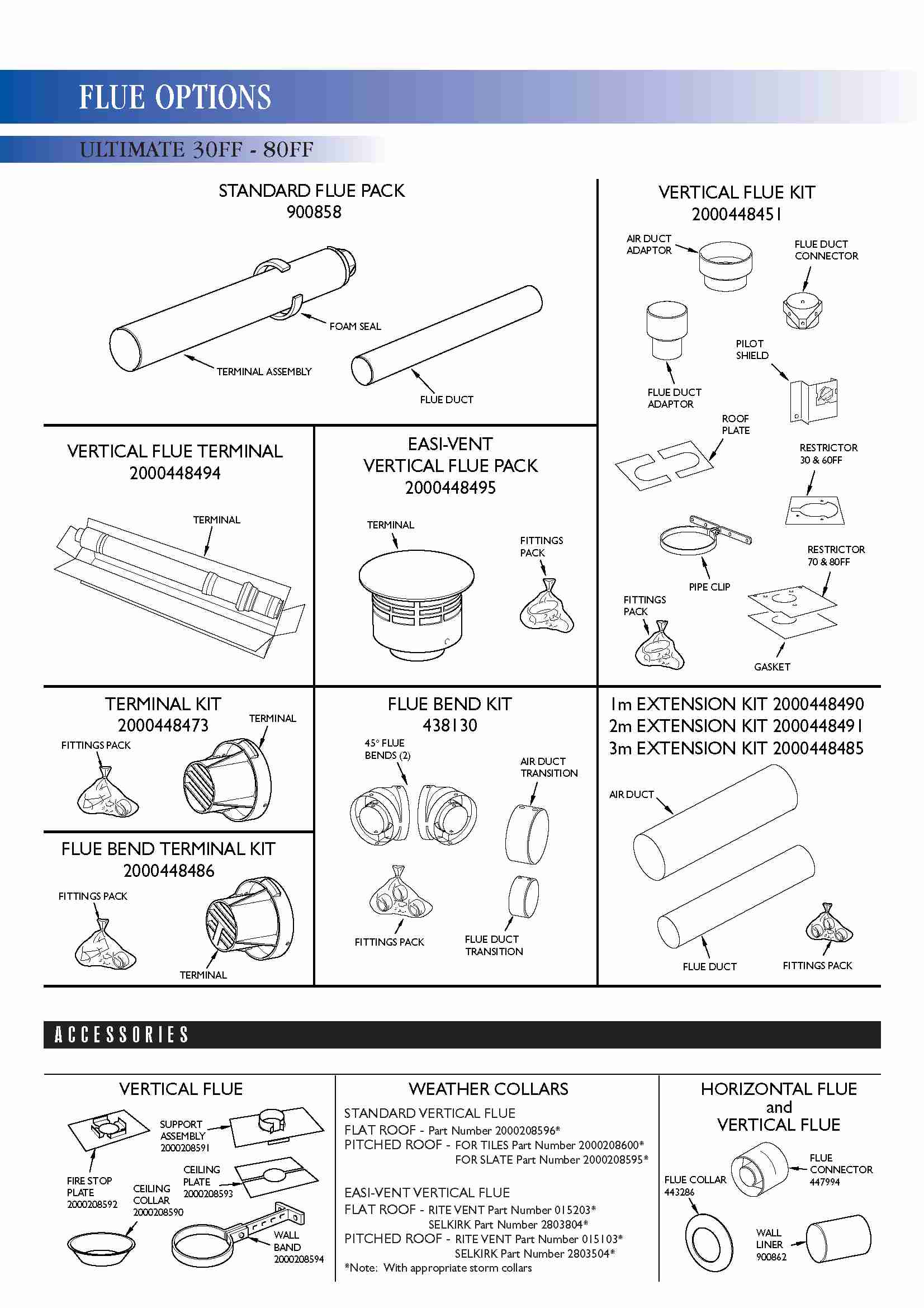
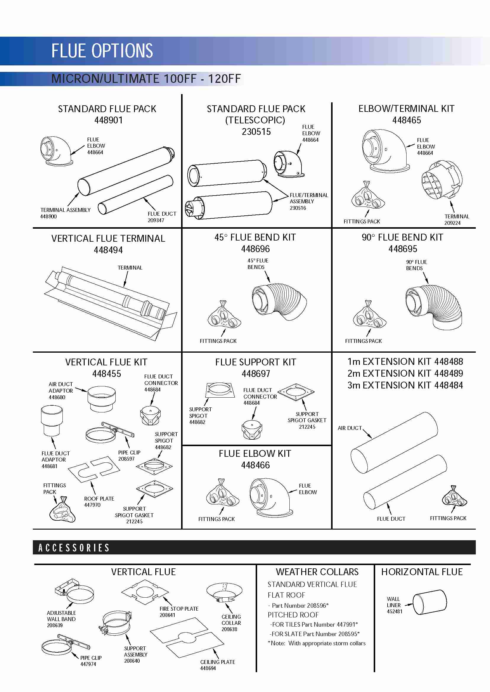
Flue Guide
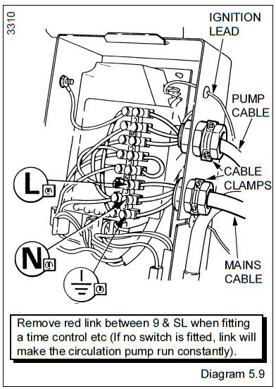
Wiring Controls
Any External controls must only be wired to interrupt the red link between terminals SL and 9. Make syure the supply cable and all external cables are secured and away from hot surfaces.
Available Literature
 Ultimate 30FF Installation and Servicing Manual Ultimate 40FF Installation and Servicing Manual Ultimate 50FF Installation and Servicing Manual Ultimate 60FF Installation and Servicing Manual Ultimate 70FF Installation and Servicing Manual Ultimate 80FF Installation and Servicing Manual Ultimate 100FF Installation and Servicing Manual Ultimate 120FF Installation and Servicing Manual