How can we help?
Having trouble? Click here to access our troubleshooting guide.
Your Question:
Micron 100FF - 120FF 1 Fuse 5 Wire Engineer Support
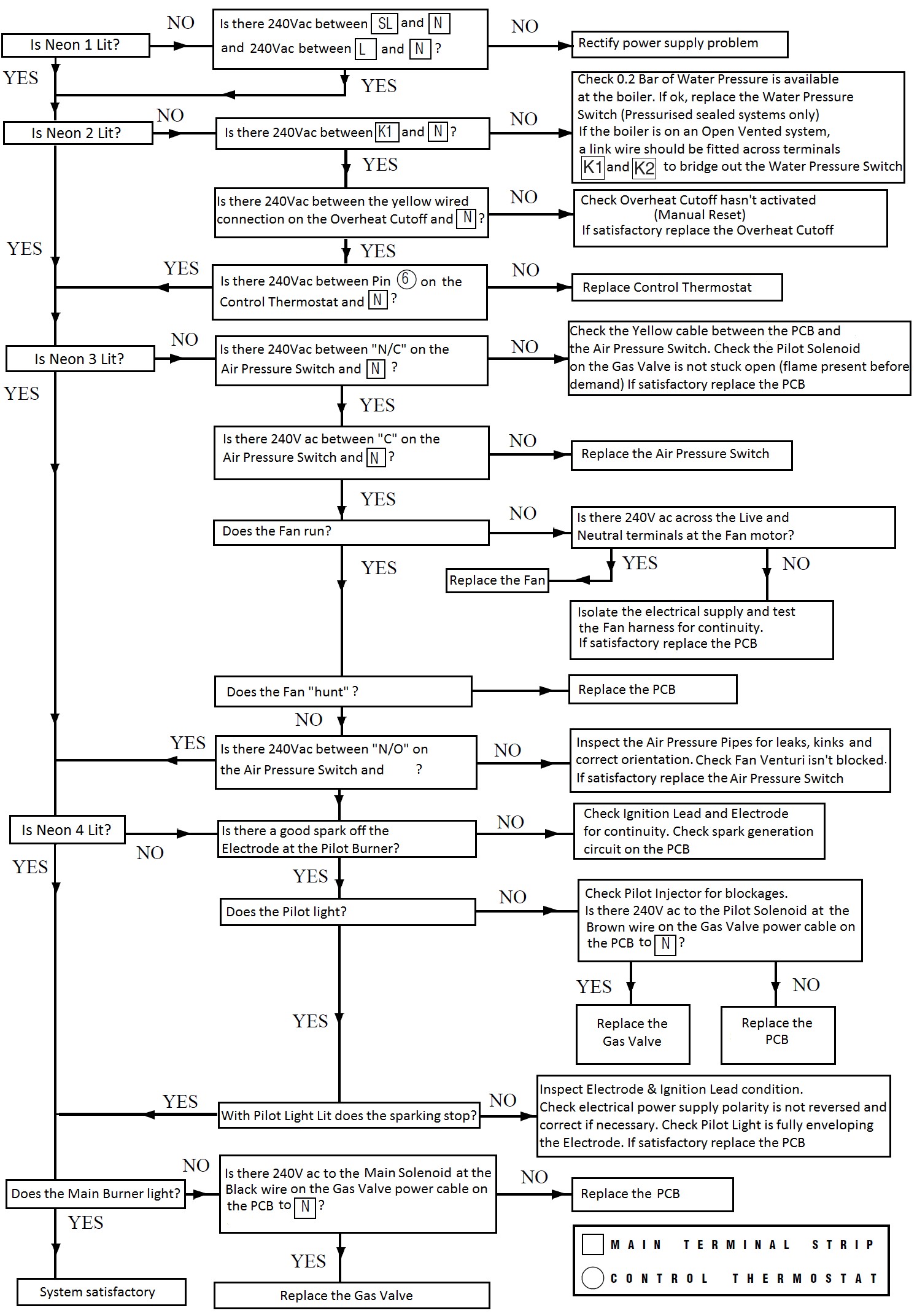
Micron 100FF - 120FF Fault Finding
Early Versions with 1 FUSE 5 WIRE PCB fitted

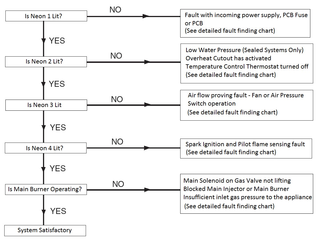
The earlier variants of the Micron 100FF - 120FF use a PCB with 5 wires coming off it and a single 1 amp fuse as shown on the above photo. The Pump and the Pump Overrun function are controlled off the Boiler Thermostat on versions fitted with this PCB. The Pump Overrun is temperature controlled, and will run the Pump after the demand has ceased until the boiler temperature drops to 65 degrees celsius. There are 4 neon sequence lights on the PCB to aid fault diagnosis.
Neon Key
The 4 Neon indicators on the PCB are an aid to fault finding only. Failure of any of the Neon indicators does not warrant the replacement of an otherwise fully functioning Printed Circuit Board
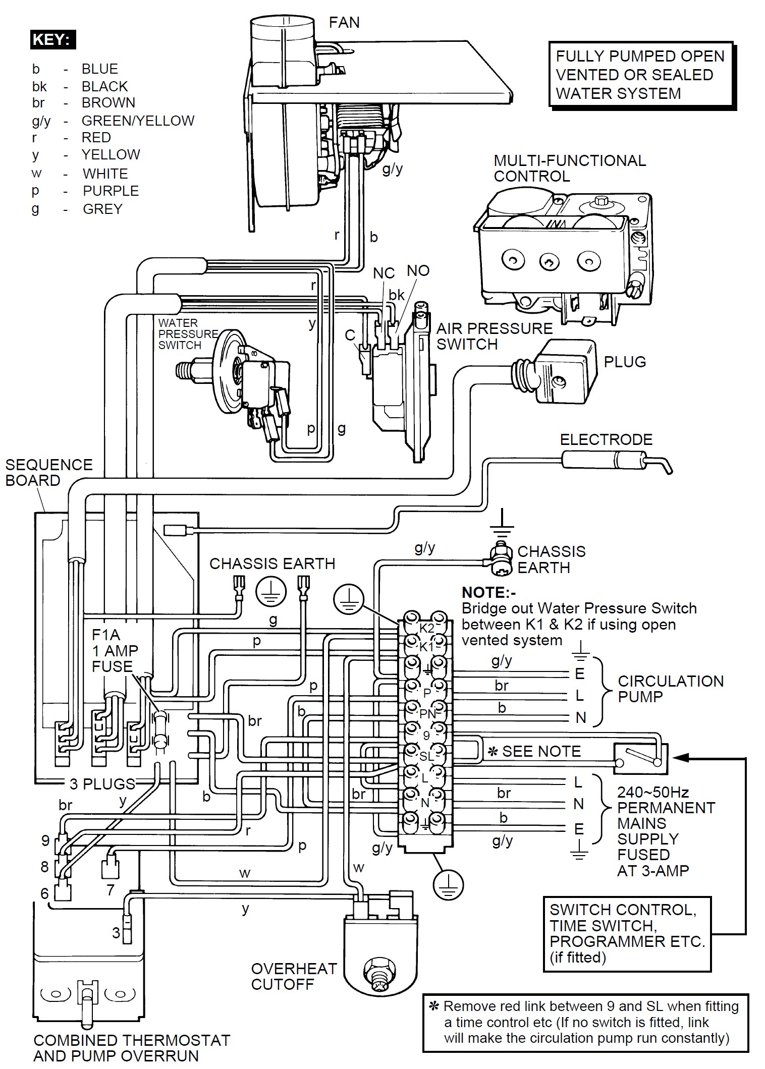
Micron 100FF - 120FF Schematic Wiring Diagram (1 FUSE 5 WIRE VERSIONS)

Component Resistances
PCB Fuse
1 Amp (Fast Blow) – Continuity (<1 ohm)
Fan
Approximately 45 ohms
Gas Valve
Pilot Solenoid (EVI to COM) 800-900 ohms
Main Burner Solenoid (EV2 to COM) 800-900 ohms
Overheat Cutoff Thermostat
Continuity (<1ohm) if ok – Open Circuit (OL) if tripped to an overheat state
Component Voltages
PCB Fuse
1 Amp (Fast Blow) – 240vac to Neutral on each side of the Fuse
Water Pressure Switch
240vac on the Grey Wire to Neutral & 240vac on Purple Wire to Neutral when the Water Pressure Switch is “made” with a minimum of 0.2bar pressure (if used on a Pressurised Sealed System) or when a link wire is fitted across contacts “K1” & “K2” on the boiler terminal strip (when used on Open Vented Systems)
NOTE – The Water Pressure Switch circuit can be tested for 240vac on Terminal “K2” to “N” and 240vac on Terminal “K1” to “N” on the boiler terminal strip if preferred
Overheat Cutoff Thermostat
240vac Input on the White Wire to Neutral & 240vac Output on Yellow Wire to Neutral (If the Overheat Thermostat hasn’t tripped)
Temperature Control Thermostat
Permanent Live supply to stat on to Pin 9 (Brown Wire)
Switched Live supply from system controls on to pin 8 (Red wire)
Pump Live supply from stat to Pump on Pin 7 (Purple wire)
Temperature On/Off contacts are 240vac Input on to Pin 3 (Yellow wire) and 240vac Output from Pin 6 (Yellow Wire) with stat ON (set point higher than boiler temperature)
Air Pressure Switch
Works on 240vac inputs and outputs.
Before the APS makes there will be 240vac on the Yellow (N/C) wire to N, and 240vac on the Red (C) wire to N. When the Fan runs and the APS makes there will be 240vac on the Red (C) wire to N, and 240vac on the Black (N/O) wire to N.
The APS can also be tested with the power off in the following manner if required:
In the rest position you should record Continuity across the COM & N/C contacts on the Air Pressure Switch,
In the “made” position you should record continuity across the COM & N/O contacts on the Air Pressure Switch
APS Wire Colours:
Red = COM
Yellow = N/C
Black = N/O
APS Pipework Orientation:
At the APS:
Red Pipe = Bottom Connection
Clear Pipe = Top Connection
At the Fan:
Red Pipe = Rear Connection
Clear Pipe = Front Connection
Fan
240vac across the Red (L) & Blue (N) Wires on demand at either the Fan motor or the PCB Plug
Gas Valve
(This is tested on the gas valve power feed plug on the PCB)
Pilot Solenoid – 240vac on the Brown Wire to Neutral on demand
Main Burner Solenoid – 240vac on the Black Wire to Neutral once the pilot flame rectification has proved (Neon 4 lit on the PCB)
Feed To External System Pump
240vac on Terminal “P” to Neutral on the Boiler’s electrical terminal strip. This voltage comes from the Purple Wire Pin 7 on the Temperature Control Thermostat to power the external system pump, and should be present on demand from external heating controls and when the temperature controlled pump overrun function is active.
Water Pressure Switch (Pressurised Sealed Systems Only)
240vac on connection K2 to N on the terminal strip (Feed in to the Switch)
240vac on connection K1 to N on the terminal strip (Feed out from the Water Pressure Switch when the pressure is at least 0.2bar on pressurised sealed systems)
NOTE – A link wire should be placed across terminals K1 & K2 on the boiler terminal strip to bypass the Water Pressure Switch circuit when the boiler is fitted to an Open Vented System.
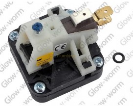
**There are 2 versions of the Water Pressure Switch as shown below. Both styles of switch are interchangeable with each other.
The older “Disc” type (Wires go on terminals “C” & “N/O)
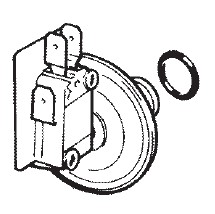
The newer “Square” type (Wires go on terminals “1” & “2”)
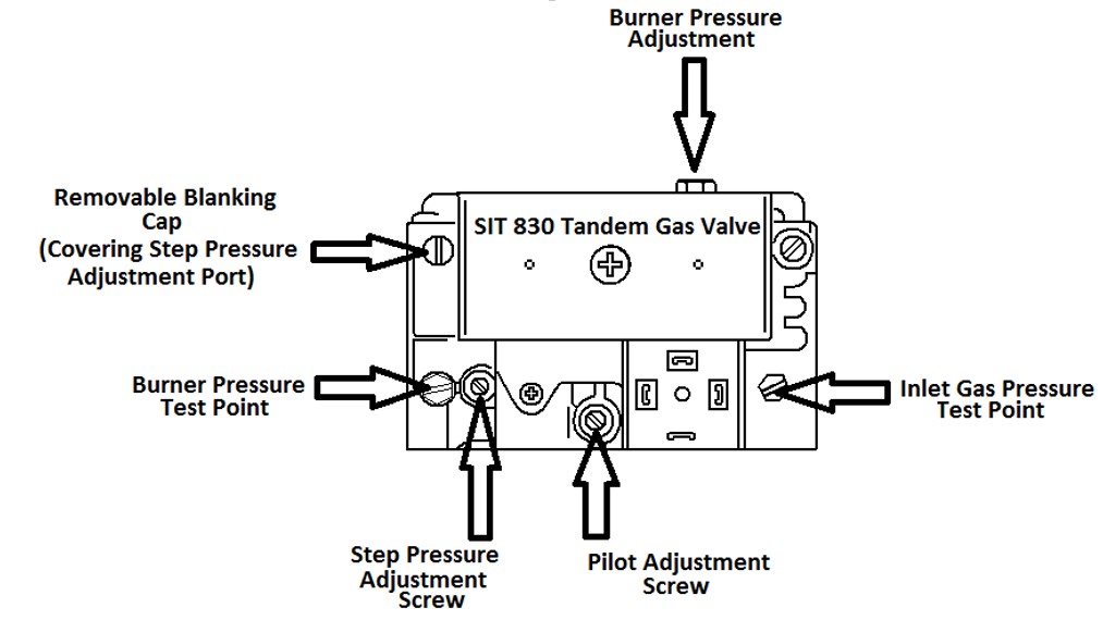
Gas Valve Ignition (Step) Pressure Adjustment
The Micron 100FF - 120FF uses a SIT 830 Tandem Gas Valve which has a step pressure setting on it. This step pressure function allows the main burner to light at a lower (ignition) pressure briefly before stepping up to maximum burner pressure. This function is designed to prevent hard ignition issues.
The step pressure on the Micron 100FF - 120FF boilers should be set at 6mbar. To set up or check this pressure proceed as follows:
1 – Connect a Manometer to the Burner Pressure Test Point
2 – Remove the blanking cap from the Step Adjustment Port on the left hand side of the Gas Valve
3 – Cover the Step Adjustment Port with your thumb (to make it air tight)
4 – Place a demand on the boiler and when it fires it will be locked at the step pressure setting which should be set at 6mbar. If it requires adjustment, whilst keeping your thumb over the StepAdjustment Port, turn the Step Pressure Adjustment Screw until you record 6mbar on yourManometer. When 6mbar is achieved, release your thumb from the Step Pressure Adjustment Port and the pressure should then increase to the maximum burner pressure as shown on the appliance Dataplate (If the maximum burner pressure requires adjustment use an 8mm openended spanner to turn the Burner Pressure Adjustment Nut on the top of the Gas Valve)
5 – Replace the blanking cap on the Step Adjustment Port, remove Manometer and check for gas tightness.